This Website is not fully compatible with Internet Explorer.
For a more complete and secure browsing experience please consider using Microsoft Edge, Firefox, or Chrome
Improvement of Cooling Efficiency of E-Motors using Moving Particle Simulation, A Mesh-Less CFD Method
Massimo Galbiati (EnginSoft SpA, Italy);
Abstract
The use of Moving Particle Simulation (MPS) has diffused for the last years starting from the automotive sector, mainly for powertrain applications, like the simulation of oil splashing and lubrication of engines and transmissions. The benefit of this method is the capability to simulate free-surface flows and liquid jets in very complex geometries, like a complete transmission or engine, in a short modeling and simulation time. This is feasible thanks to the meshless nature of MPS.
In this paper the simulation process of oil cooled e-motor will be presented. Oil cooled e-motors are being developed by different companies, both in the automotive and aerospace sectors, to replace IC engines and conventional fuels. The trend and need to increase the power density of e-motors force companies and designers to use internal cooling, by injecting the coolant directly inside the motor. At the same time, the search for efficiency and lighter components pushes the designers towards integration of the e-motor with the transmission, so that one of the most common solution is to use the transmission lubricant as the cooling fluid for the e-motor.
In this search for efficiency and performance, the use of MPS can support the design of oil injection and the optimization of cooling efficiency. Most of the players in this sector are working on the development of new designs and the capability to simulate and predict the behavior of the system in a fast way and at the early stages of the design is of paramount importance to reduce the number of prototypes and to shorten the development time.
1. Introduction to Moving Particle Simulation (MPS)
The Moving Particle Simulation is a deterministic Lagrangian method to solve the Navier-Stokes equations in incompressible conditions. It is a mesh-less method based on the idea of discretizing the fluid with particles. The particle size is equivalent to the mesh size in Finite Volume CFD and it defines the spatial discretization of the fluid volume. MPS simulations are always transient and allow calculating not only the pressure and velocity of the fluid, but also temperature and heat transfer, by solving the energy equation.
The MPS solver can also calculate the Heat Transfer Coefficient (HTC) distribution on the walls of the system. This is done by using Nusselt number correlations with the local Reynolds and Prandtl numbers Nu=Nu(Re,Pr). The main benefit of the HTC calculation with respect to the temperature solution is that the HTC can be calculated even with a short transient run, without waiting for the temperature development and stabilization that usually takes much longer than the stabilization of the flow.
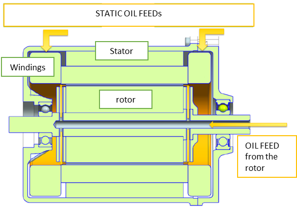
The HTC calculation and the mesh-less nature of the MPS method are particularly interesting when it comes to the design of high power density e-motors. These systems are very complex from the geometrical point of view and the current trend is to design running-wet e-drives. This means that in order to have a proper cooling level, the coolant is directly injected into the e-motor, like shown in Figure 1. The cooling oil is injected by means of internal channels and holes in the rotor and by means of static inflows. The oil impinges on the windings to reduce their temperature.
This is where the MPS method can support and give an advantage to the designers. The MPS can simulate easily and in a short time, very complex rotor and windings geometries with oil jets / sprays and free surface flows and it can predict the heat transfer coefficient distribution on the surface of the windings.
Figure 1: layout of a running-wet oil-cooled electric motor
2. Simulation process of oil flow and temperature prediction
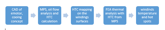
During the design process of cooling concepts the procedure shown in Figure 2 is applied. Different oil injection concepts are compared by simulating the oil distribution in the rotor channels, by calculating the HTC distribution and by predicting the average and peak temperature values on the vital parts of the e-drive.
Figure 2: design process of an oil-cooled electric motor
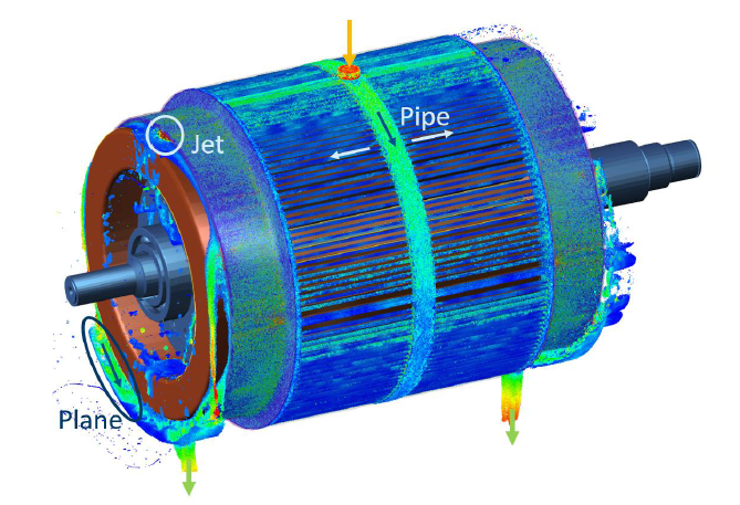
Figure 3 shows the oil flow in an e-motor with three areas, where the characteristics of the flow are different. In some areas, the flow is directly impinging on the surface of the windings and has a high cooling efficiency. In other regions, it is a pipe flow, in others it is a film flowing parallel to the wall. In all these areas a different Nusselt number correlation Nu=F(Re, Pr) should be used, based on the local flow conditions. This aspect is considered by the MPS method by implementing Nusselt number correlations based on the local velocity components and conditions (laminar versus turbulent)
Figure 3: oil flow in a running-wet e-driver (Courtesy of Sebastian Jugelt, IAV GmbH, Germany)
3. Windings temperature predictions
The procedure described above has been applied and validated both in terms of oil distribution inside the rotor channels and in terms of temperature of the windings. Figure 4 shows the windings temperature map coming for the FEA thermal simulation, with HTC boundary conditions from the MPS fluid simulation.
Figure 4: temperature distribution on the windings of an e-drive
For the e-motor shown in Figure 4, the average and peak temperatures for three cooling designs have been compared. The difference between the three configurations is the oil flow rate distribution. Table 1 shows that Design A is the cooling solution with the minimum temperature values.
Cooling design
Peak T [°C]
Average T [°C]
Design A
124.9
104
Design B
135
106
Design C
129
105
Standard Motor Design Software (Design A)
122
115
Table 1: Comparison of windings peak and average temperature between three different design and validation of predictions against a motor design software.
4. References
L. Martinelli, M. Hole, D. Pesenti, M. Galbiati (2018). Thermal Optimizations of e-drives using Moving Particle Simulation Method. SIA Powertrain Conference, [online]
M. Galbiati (2017). Oil splashing, lubrication and churning losses prediction by moving particle simulation, NAFEMS World Conference, [online]
S. Koshizuka, A. Nobe, Y. Oka (1998). Numerical analysis of breaking waves using the moving particle semi-implicit method. Int. J. Numer. Meth. Fluids 26, 751–769