This Website is not fully compatible with Internet Explorer.
For a more complete and secure browsing experience please consider using Microsoft Edge, Firefox, or Chrome
Structural Integrity and Reliability Assessment for Actuated Subsea Valves
Ing. G. Malinverno (Advanced Technology Valve SpA, Italy);
Abstract
Being active in the oil & gas sector for several years, ATV designs and manufactures engineered actuated valves for some of the most demanding applications in the offshore sector, such as installations HP/HT in "deep" and "ultra-deep waters" and HIPPS applications.
A high-integrity pressure protection system (HIPPS) is a safety-instrumented system (SIS) that will shut-off the source of overpressure, preventing the loss of functionality and structural integrity in a chemical plant, oil refinery, or a subsea well. Actuated valves used in such systems shall have a documented and validated level of reliability, against systematic and random failures.
Different tools are used to assess the actuated valve performance, ranging from traditional static structural analysis, based on stress assessment, to more detailed FE analysis of fracture mechanics, to Monte Carlo simulation to predict the probability of failure.
FMEDA and reverse fault tree analysis helps discover hidden correlation between failure modes and evaluate the assembly failure rate required to verify the safety integrity level – given the high number of components and the probabilistic nature of failure mode, numerical method based on Monte Carlo simulations is an effective way to analyse the combination of failure modes and their effect on valve’s performance.
Furthermore, the combined use of these tools leads to a better prediction of system behaviour and they help identify the appropriate measures to improve the design and validate the product, e.g. results from fatigue and fracture mechanics analyses can be used in SIL assessment whereas failure rates can be used in design phase to identify the most critical components and optimize the effort required to increase product quality.
1. High-integrity pressure protection system (HIPPS) overview
For a process plant, like a refinery, a High-Integrity Pressure Protection System or HIPPS is equivalent of a pressure relief valve for an assembly. Indeed, it is defined by ISO/TR 12489 as a nonconventional, autonomous, safety instrumented system with sufficiently high safety integrity to protect equipment against overpressure.
As a safety-instrumented system (SIS), international standard and regulations require that the HIPPS system shall have a documented and validated level of reliability. Furthermore, the traditional maintenance approach is forbidden by the environment and the high demanding operation al conditions. Thus, the structural integrity and reliability assessment play a relevant role in the design phase and the product verification and validation (IEC:2010).
2. Integrity and reliability assessment overview
As a relevant part of a HIPPS system, the final element, i.e. the assembly given by the valve and its actuator, shall be verified against any potential failure that could occur. Ideally, the assessment can be divided in two main different approaches, i.e. the protection against systematic failures and the protection against random failures.
The protection against systematic failures can be summarized as the typical design approach based on deterministic formulas and a structured quality management, e.g. the product shall be properly sized, environmental and operational conditions duly considered, etc., whereas the protection against random failures involves statistical methods and an overall view of “what can go wrong”, e.g. probabilistic failure rates, cascade effects, and human factors.
3. Structural integrity assessment
The harsh environment and the demanding operating (design) conditions, require that the pressure vessel, as the actuated valve can be modelled, shall be verified against different failure modes, nominally the classical collapse due to exceeding loads, buckling phenomena or cyclic loads. Indeed, fatigue analysis is mandatory as per relevant applicable law (i.e. Machinery directive) not only as per product code (i.e. API 17TR8 and ASME BPVC, sec. VIII).
Paradoxically, being the actuated valve seldom operated (less than thousand cycles in a classical life of 30 years) but at high loads, the cyclic loads play a relevant role in the design. This cyclic load condition (Low Cycle Fatigue - LCF) is very demanding for the alloys used in the subsea valve, mainly duplex stainless steel and high strength nickel alloys and it involves the use of elastic plastic material models in the FE analyses (Krupp:2014).
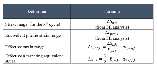
The workflow associated with the fatigue analysis can be summarized as follows: perform a preliminary analysis to identify the stress amplitude, given (or supposed) the load histogram, apply a counting method as the “rainflow” to extract the equivalent stress ranges sequence, run a dedicated FE analysis to retrieve stresses and plastic strains. The alternate equivalent stress is consequently evaluated as weighted sum of these two quantities. Finally, from the material SN curve, the allowable number of cycles is retrieved and thus the accumulated damage as per Miner rule can be assessed.
Table 1: Equivalent plastic strain and equivalent alternate stress calculation as per ASME BPV code, sec. VIII div. 2 part 5.5.4 and API 579-1 (API:2007).
It is noteworthy to point out how the plastic strain play a relevant role in this procedure, since the failure in the LCF physical mechanism is mainly driven by the local plastic strain and, consequently, from a numerical point of view the contribution of plastic strain to the equivalent alternate stress is quite relevant.
Furthermore, the use of the correct material model is a major critical point of this type of analysis, since if the classical monotonic stress-strain curve could be taken for granted, the cyclic stress-strain curves are still a source of uncertainty, as on the other hand the SN curves themselves.
4. Safety Integrity Level assessment
Roughly speaking, the Safety Integrity Level can be quantified by the probability of failure on demand, related to the assembly failure rate, and the functional requirements of the actuated valve may be verified by design reviews, such as FMECA and / or various types of testing, e.g. factory acceptance testing (IEC:2010 and Brunelli:2019).
The FMECA lists the possible failure modes associated with each component of the actuated valve and their estimated failure rates. In fact, assembly failure rate is merely given by the weighted sum of the components failure rates.
Usually, components and subcomponents failure rates are retrieved by international sources like OREDA or EXIDA, based on feedbacks provided worldwide by users and manufacturers. However, since these values are quite high and lead to oversized solutions, internal testing, field feedbacks, and numerical analysis can be used to build an internal reliability database.
Even if a FMECA shall be done involving all relevant people, to identify all possible failure modes, the method can be easily automated and implemented within common office tool like spreadsheets or in little more elegant solutions like dedicated in-house programs (e.g. based on python).
Additionally, a reverse fault tree analysis can be carried out to discover any superposition effects that has not been discovered through the FMECA, retrieve a better estimation of total failure rate, and, eventually, optimize the project, also during the design phase, simulating the behaviour of different solutions and identifying the critical path in association with Monte Carlo simulations (Rajasankar:2003 and Szkoda:2016).
5. Conclusion
The combined use of deterministic and statistical approaches leads to a better prediction of actuated valve reliability, helps identify the appropriate measures to improve the design, and validates the product.
Furthermore, results obtained in an assessment can be reused in a different contest, e.g. results from fatigue and fracture mechanics analyses are used not only to estimate the life of the components but, also, to better estimated the failure rates. Indeed, combined methods give valuable data to be used in design phase, identifying the most critical components and optimizing the effort required to increase product quality
6. References
American Petroelum Institute (2007). Fitness-For-Service:API 579-1
Brunelli, Alessandro, Andreolli, Fabio (2019). Sicurezza funzionale degli impianti industriali. Progettazione dei Sistemi Strumentati di sicurezza (SIS) in conformità alle norme IEC/EN 61508 & 61511:Editoriale Delfino
International Electrotechnical Commission (2010). Functional Safety of Electrical/ electronic/programmable Electronic Safety-related Systems:IEC,61508.
Kaczor, Grzegorz, Młynarski, Stanisław, Szkoda, Maciej (2016). Verification of safety integrity level with the application of Monte Carlo simulation and reliability block diagrams: Journal of Loss Prevention in the Process Industries 41 (2016) 31e39
Krupp, Ulrich, Alvarez-Armas Iris (2014). Short fatigue crack propagation during low-cycle, high cycle and very-high-cycle fatigue of duplex steel – An unified approach: International Journal of Fatigue 65 (2014) 78–85
Rajasankar, J., Iyer, N.R., Appa Rao, T.V.S.R. (2003). Structural integrity assessment of offshore tubular joints based on reliability analysis: International Journal of Fatigue 25 (2003) 609–619